
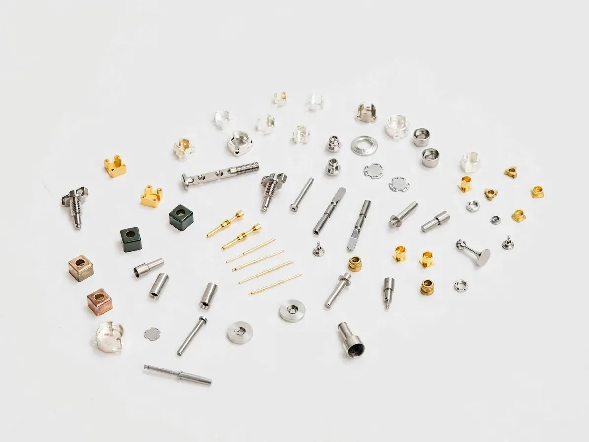
When engineering micro-components for medical devices, aerospace sensors, or telecommunications, traditional CNC lathes often hit a physical wall. As parts get smaller, longer, and thinner, the pressure from the cutting tool causes the material to bend or vibrate—a phenomenon known as deflection.
The solution to this engineering roadblock is Swiss-Type CNC Machining.
At Aizhuo Precision, our advanced Swiss-type turning centers (equipped with live tooling) are engineered specifically to manufacture highly complex, tight-tolerance parts in a single setup. However, to truly maximize the precision and cost-efficiency of this technology, engineers must design with the machine’s unique mechanics in mind.
Here is your comprehensive Design for Manufacturability (DFM) guide for Swiss-Type Machining.
To design for a Swiss lathe, you must understand how it operates.
In a conventional CNC lathe, the workpiece is held firmly at one end by a chuck, and the cutting tool moves along the spinning material. If the part is long and thin, the unsupported end will deflect away from the tool.
A Swiss-type lathe solves this by using a Guide Bushing. Instead of the tool moving across the part, the spinning bar stock is fed through the guide bushing, past a stationary cutting tool. Because the cutting action always happens mere millimeters from the support of the guide bushing, deflection is virtually eliminated. This allows for the machining of incredibly slender parts with extreme precision (often holding tolerances of ±0.005mm or tighter).
Traditional lathes struggle with any Length-to-Diameter (L/D) ratio over 3:1 or 4:1. Swiss machines, however, thrive on high L/D ratios, easily handling 10:1, 20:1, or even higher.
Modern Swiss machines at Aizhuo feature Live Tooling (Mill-Turn capabilities). This means the machine has miniature milling cutters and drills that can work on the part while it’s still in the lathe.
Drilling deep blind holes in micro-components is a nightmare for chip evacuation. If chips get packed at the bottom of a 1mm diameter hole, the tiny drill bit will break, halting production.
Because Swiss machining is so precise, engineers are often tempted to blanket the entire CAD drawing with incredibly tight tolerances.
While our Swiss centers can routinely hold ±0.005mm, applying this to non-critical dimensions drastically increases cycle times, tool wear, and inspection costs.
A critical rule in micro-manufacturing is: If you can’t measure it, you can’t guarantee it.
Traditional CMM (Coordinate Measuring Machine) touch-probes are often too large—or apply too much physical pressure—to accurately measure slender Swiss-turned parts without bending them.
This is where Aizhuo’s Advanced Metrology Lab bridges the gap. We utilize non-contact OGP optical comparators and Keyence Automated Optical Inspection (AOI) systems. This allows us to verify sub-micron dimensions, check for micro-burrs, and provide 100% automated sorting for high-volume Swiss machining runs without ever physically distorting your parts.
Swiss-type machining is the ultimate solution for complex, high-volume miniature parts—if engineered correctly. Whether you are scaling up production for a surgical instrument or a complex aerospace connector, our engineering team is ready to review your CAD and optimize your DFM.